<< Home page >>
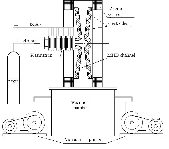
Schematic diagram of experimental MHD facility is shown in Fig.1, and the side view is shown in Fig.2 (a, b). The MHD facility consists of a magnet system, a vacuum system composed by a vacuum chamber and vacuum pumps for pressure reduction, a system of gas supply with argon storage, electrical power supply, a cooling system, control, measurement & recording system, a loading unit, a source of the working gas (plasmatron), a seed supply system, and a subject of research (linear or disc MHD channel).
Fig. 1. Experimental disc MHD facility
The experimental MHD facility operates in the following way. Argon is supplied from a gas cylinder to the plasmatron where it is heated by DC electric arc. The heated and electrically conductive gas is supplied from the plasmatron nozzle to the MHD channel, which is hermetically connected with a vacuum chamber. Then argon is exhausted through the system of vacuum pumps into atmosphere. The transverse magnetic field in the MHD channel is created by the magnet system. General performances of the experimental MHD facility are given in Table 1.
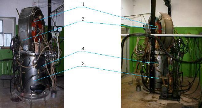
Fig.2a. Left-hand side view of MHD facility Fig.3b. Right-hand side view
1 – magnet system; 2 – main vacuum chamber; 3 – disc vacuum chamber; 4 – measuring portholes
Table 1. General Performances of Experimental MHD Facility
| Parameter | Unit |
Value |
| Working gas | Argon |
|
| Working gas mass flow rate | g/s |
5 |
| Magnetic field induction | T |
0.3 |
| Plasmatron power | kW |
150 |
| Parameters at the MHD channel inlet: | ||
| Mach number | 2 |
|
| Argon velocity | m/s |
2500 |
| Average argon pressure | Pa |
103 |
| Hall parameter | 2 – 3 |
|
| Average electron temperature | K |
9000 |
| Vacuum chamber capacity | m3 |
2 |
| Vacuum chamber pressure | Pa |
~10 |
| Mass flow rate of cooling water | m3/h |
8 – 9 |
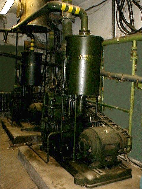
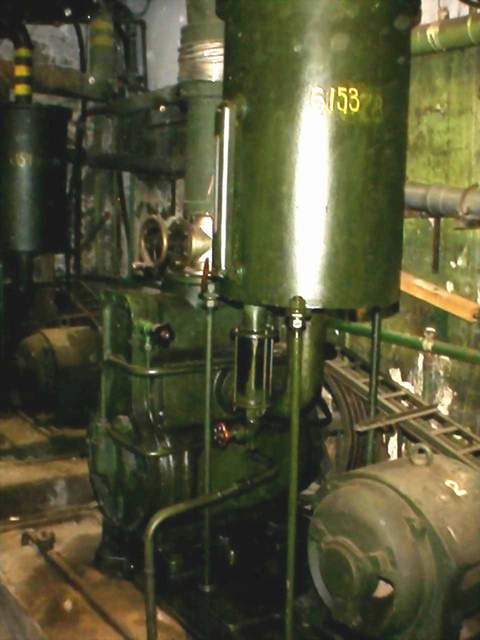
The vacuum system of the experimental MHD facility consists of main cylindrical vacuum chamber of 2 m3 capacity (item 2, Fig 2a,b), and additional disc vacuum chamber (item 3, Fig 2a,b) installed on the main chamber and designed for investigations of the disc MHD channel (the linear MHD channel is installed directly on the cylindrical vacuum chamber). The reduced pressure of 10 Pa is provided by two vacuum pumps (Fig.3 a, b) with the evacuation rate of 500 l/s. When the plasmatron operates, the chamber pressure is 100 Pa. The vacuum chambers are equipped by portholes and sealed outputs for connection of different sensors. The side surface of the chambers is two-layered with pumping of the cooling water between the walls.
a) b)
Fig.3. Vacuum pump
The hydraulic system provides the water cooling of heat-beat areas of the plasmatron, MHD channels, and the vacuum chamber. It consists of a water pump (Fig.4) providing the water flow rate of 8 m3/h at the pressure of 9 atm, pipelines with flow meters and valves installed.
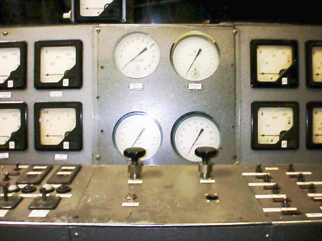
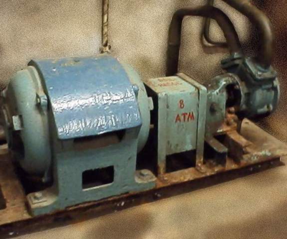
Fig.4. Water pump Fig.5 Control panel of the gas supply system
The working gas flows from the plasmatron to the accelerating disc nozzle in the axial horizontal direction with the following flow turn in the intermediate chamber of the accelerating nozzle. The low temperature argon plasma is created by DC electric arc plasmatron. The argon flow is heated in the plasmatron by two-stage DC arc. The discharge stabilization is provided by solid walls of diaphragms restricted the arc diameter, and by flow swirl. Pressure in the plasmatron channel is less than atmospheric pressure for reducing the heat flux to the high-heat components of the plasmatron design and increasing its operating life. In this case the plasma jet pressure at the nozzle outlet is 3·104 Pa. The plasmatron has the following operating parameters: electric current up to 1300 A, voltage of 100 V, diameter of stabilizing channel of 20 mm, the channel length of 200 mm, argon flow rate up to 5 g/s. Testing of the plasmatron at the power level up to 150 kW performed in the MHD facility proved its reliable and long operation without notable erosion of electrodes.
The gas supply system is designed for feeding the working gas (argon) into the plasmatron. It consists of a manifold of standard cylinders with commercial purity argon at pressure of 150 atm, pipelines, pressure gauges, and argon flow sensor. The control panel of the gas supply system is shown in Fig.5.
The PC based control, measuring and recording system of the MHD facility consists of a set of sensors and instruments for the measurement of parameters of MHD channel and various components and systems of the MHD facility. It performs an automatic recording of the parameters measured, as well as a control of the facility run. The view of the system display is shown in Fig.6.
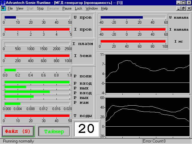
Fig.6. Typical display of control, measuring and recording system.
The power-supply system is designed for electrical power supply of the plasmatron, the magnet system, the plasmatron triggers, and process equipment of the MHD facility. Separate components of the power-supply system are shown in Figs. 7 – 8.
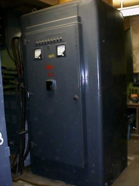
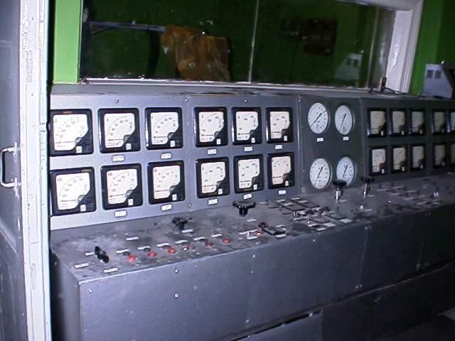
Fig.7. AC/DC converter Fig.8. Control panel of the power-supply system
The seed injection system (Fig.9) is designed for injection of the ionized seed into the MHD channel, if an increasing of the electrical conductivity of working gas is required.
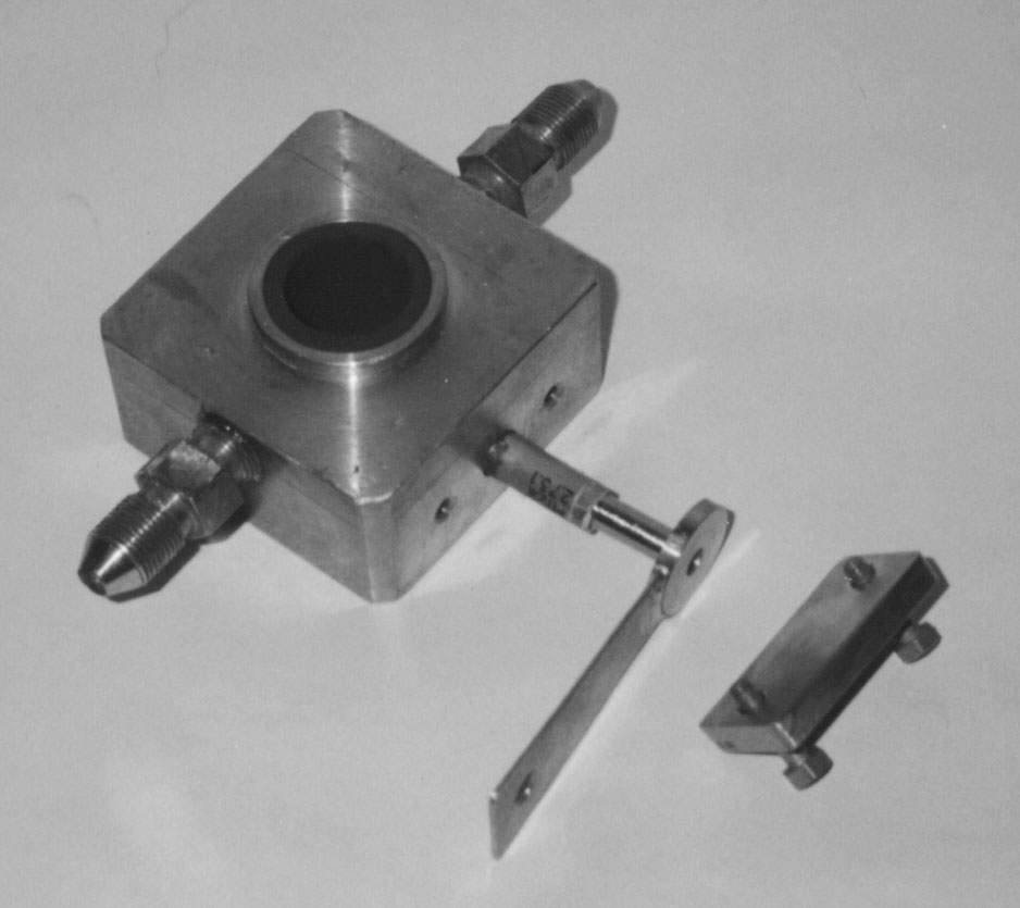
Fig.9. Components of the ionized seed injection system
The loading unit is designed for a loading of the MHD channel within the load factors specified.
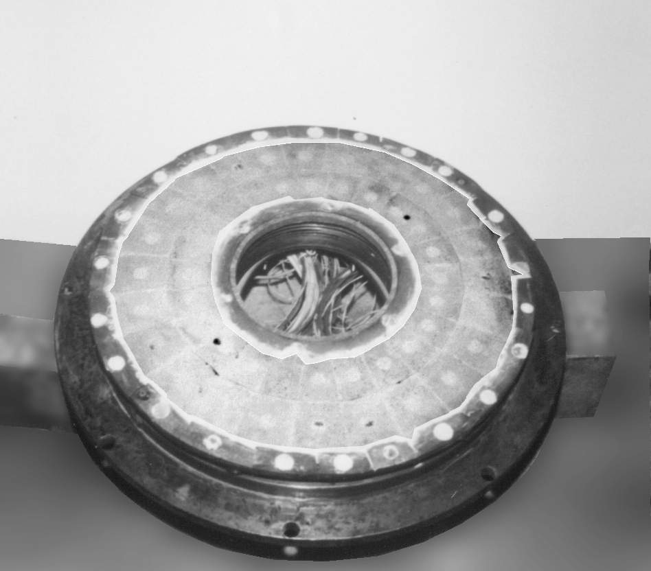
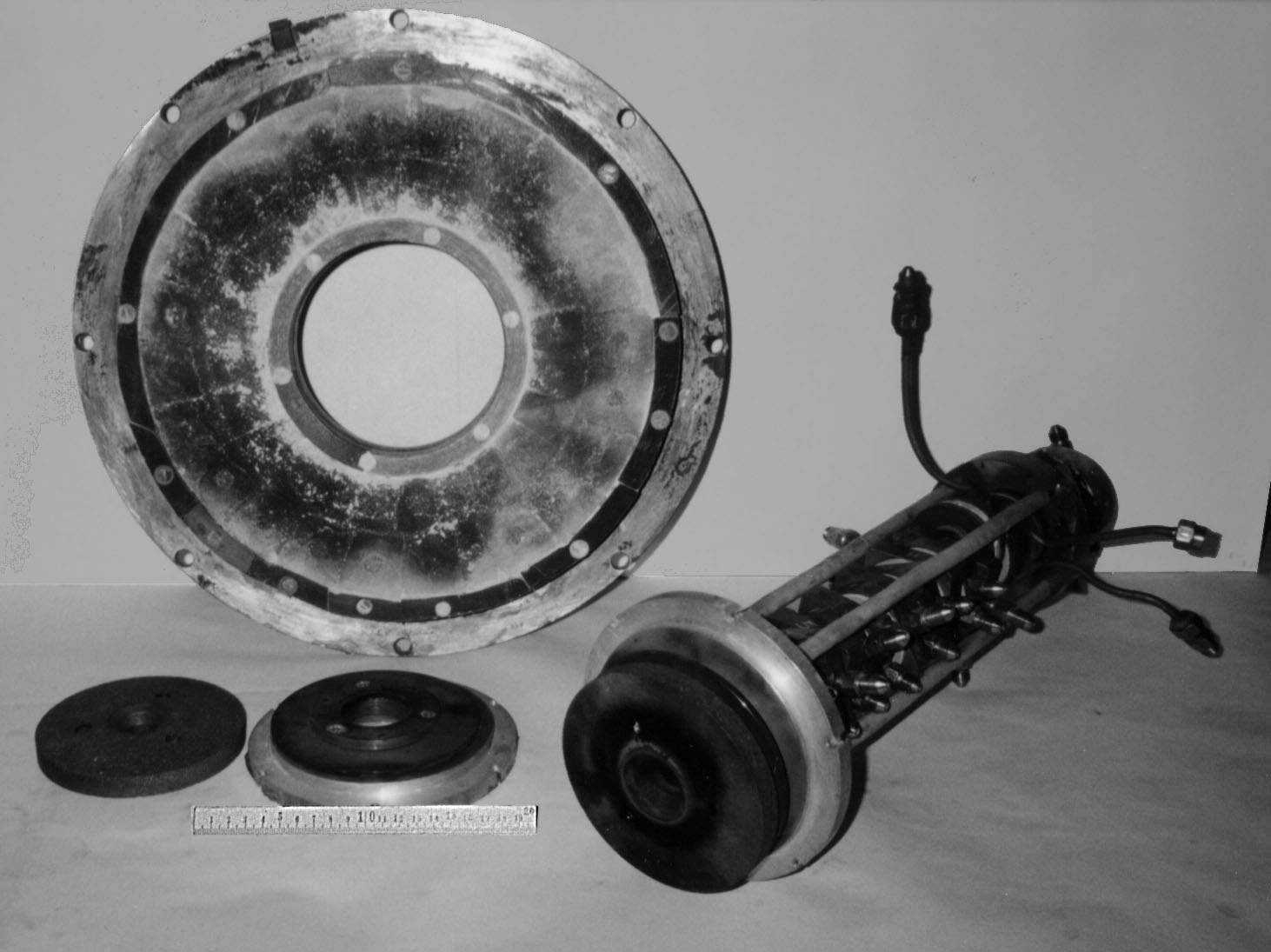
Fig.10. Wall assembly of the disc MHD channel Fig. 11. Components of disc MHD generator
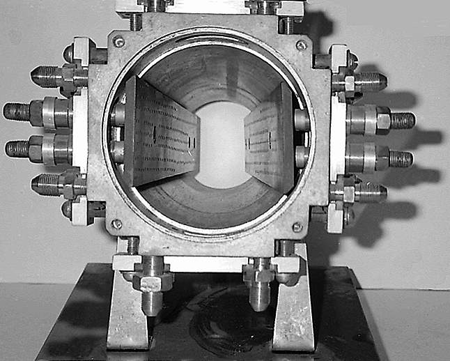
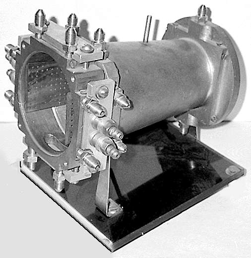
Fig.12. Linear MHD channel (front view) Fig.13. Linear MHD channel (side view)
2. Research capabilities of the experimental MHD facility.
For a purpose of determination of a possibility of application of the experimental data obtained at the experimental MHD facility for the full-scale MHD generators a comparison of ranges of variation of simulation criteria in the small-scale experimental MHD facility and full-scale MHD generators of output power of 10-50 MW fired by combustion products of liquid chemical fuels. Table 2 shows results of this comparison
Table 2. Comparison of simulation criteria for the small-scale and full-scale MHD generators
Group of criteria |
Criterion |
Range in the full-scale MHD generator |
Range in the small-scale MHD facility |
Coincidence of the ranges |
| 1-st group (non-viscous flows, volume effects) |
Mach number | 2 – 3 |
1.5 – 2.5 |
+ |
| Stewart number | 1 – 3 |
1 – 2 |
+ |
|
| Loading factor | 0.6 – 0.8 |
0.6 – 0.8 |
+ |
|
| Hall parameter | 1 – 3 |
2 – 3 |
+ |
|
| 2-nd group (viscous flows, boundary layer, wall phenomena) |
Reynolds number | 106 |
400 |
- |
| Prandtl number | 1 |
1 |
+ |
|
| Hartmann number | 103 |
10 |
- |
|
| Near-electrode voltage drop | 100 V |
10 V |
- |
|
| 3-rd group (armature reaction) |
Magnetic Reynolds number | 1 |
1 |
+ |
| Parameter of external circuits | 1 |
1 |
+ |
|
| 4-th group (criteria of efficiency of MHD process) |
Factor of short-circuit current decrease | 0.6 – 0.9 |
0.6 – 0.8 |
+ |
| Factor of decrease of open-circuit voltage | 0.6 – 0.9 |
0.6 – 0.9 |
+ |
|
| 5-th group (geometrical similarity) |
Channel size | 6 – 10 |
4 – 6 |
+ |
The table shows that the experimental MHD facility provides coincide of four groups of criteria among five ones (excluding the second group defining the dynamics of development of the boundary layers and near-electrode phenomena).
In so doing a conclusion may be made that the experimental MHD facility allows to perform the following kinds of experimental research useful for development of the full-scale MHD generators:
<< Home page >>
| Department of Pulsed MHD Power Systems & Geophysics |
|
2001 |